Table of Contents
- 1. Types and Characteristics of injection molding machine
- 2. Composition and Functions
- 3. Injection Unit Types and Structures
- 4. Clamping Unit Types and Structures
- 5. Injection molding machine Specifications
- 6. Technical Conditions and Parameters
- 7. How to Select an injection molding machine
- 8. Repair Methods and Key Points
- 9. Maintenance and Servicing
1. Types and Characteristics of Injection Molding Machine
The injection molding machine—such as plastic injection molding machine—comes in various configurations, each designed to meet specific manufacturing requirements. Understanding these types is crucial for selecting the right equipment for your production needs.
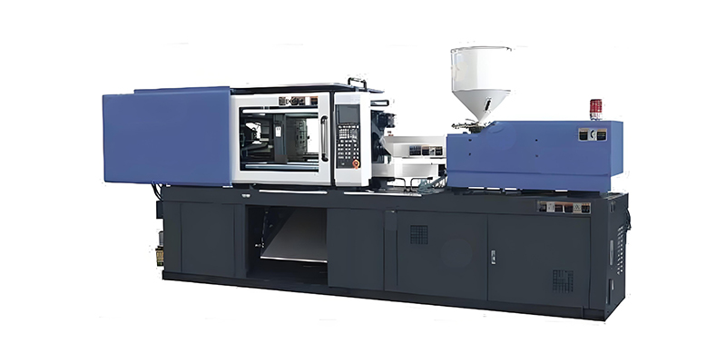
Horizontal Injection Molding Machine
The horizontal injection molding machine is the most common type, featuring a horizontal clamping unit and injection unit. This design allows for easy automation integration, efficient use of floor space, and simple operation. Horizontal machines are versatile and suitable for a wide range of applications from small components to large parts.
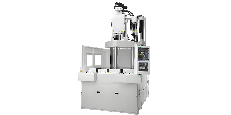
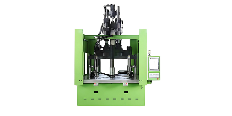
Vertical Injection Molding Machine
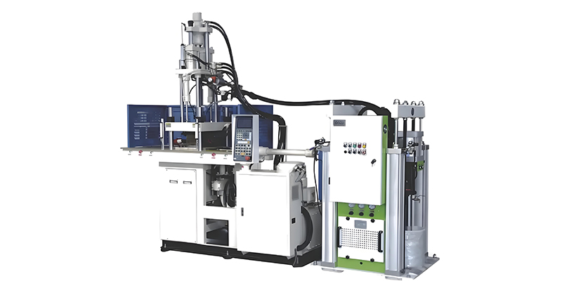
In vertical injection molding machine models, both the clamping and injection units are arranged vertically. This design offers advantages for insert molding applications, as gravity helps keep inserts in place. Vertical machines typically have a smaller footprint and are ideal for precision micro-molding and overmolding operations.
All-Electric Injection Molding Machine
All-electric injection molding machine systems use servo motors for all machine functions, eliminating the need for hydraulic systems. These machines offer superior precision, energy efficiency (up to 70% savings compared to hydraulic models), quieter operation, and faster cycle times. They are particularly suitable for cleanroom environments and applications requiring high repeatability.
Hybrid Injection Molding Machine
The hybrid injection molding machine combines the best features of hydraulic and electric systems, using electric motors for critical functions like injection and hydraulic systems for clamping. This results in a balance of precision, speed, and power, making hybrid machines a popular choice for many manufacturing environments seeking optimal performance with moderate energy consumption.
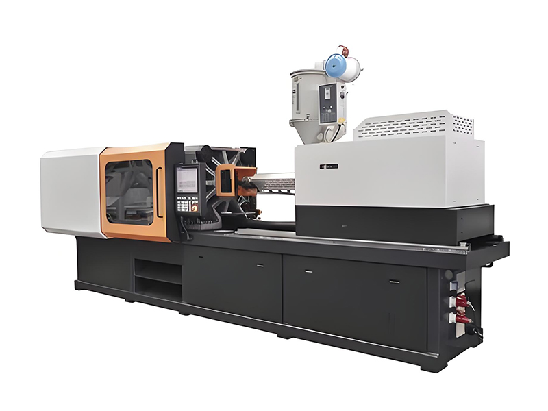
Comparison of Injection Molding Machine Types
| Machine Type | Energy Efficiency | Precision | Typical Applications |
|---|---|---|---|
| Horizontal Hydraulic | Moderate | Good | General purpose, large parts |
| Vertical | Moderate | Good | Insert molding, micro-molding |
| All-Electric | Excellent | Excellent | Precision parts, cleanroom |
| Hybrid | Very Good | Very Good | Balanced performance needs |
Specialized Injection Molding Machine Variants
- Micro-injection molding machines for tiny precision components
- Multi-material machines for complex part production
- Stack mold machines for high-volume production
- Low-pressure molding machines for sensitive electronics
2. Composition and Functions of Injection Molding Machine
An injection molding machine—one of the essential injection molding machines—consists of several key components working together to transform plastic pellets into finished parts through the injection molding process.
Injection Unit
The injection unit of an injection molding machine is responsible for melting, homogenizing, and delivering the plastic material into the mold. It includes the hopper, barrel, screw, heater bands, and nozzle. The screw rotates to convey, melt, and compress the plastic, while axial movement injects the molten material into the mold cavity.
Clamping Unit
The clamping unit secures and opens the mold during the injection molding cycle. It consists of the fixed platen, moving platen, tie bars, and clamping mechanism (hydraulic, mechanical, or electric). The clamping force must be sufficient to keep the mold closed against the injection pressure generated by the injection molding machine.
Hydraulic System
In hydraulic injection molding machine models, the hydraulic system provides the power to operate both the injection and clamping units. It includes pumps, motors, valves, cylinders, and a reservoir. This system controls the speed, pressure, and position of moving components with high precision.
Electrical System
The electrical system controls all operations of the injection molding machine, including motor operation, heater control, sensor input processing, and sequence control. It comprises the control panel, programmable logic controller (PLC), servo motors (in electric and hybrid machines), sensors, and relays.
Control System
The control system acts as the "brain" of the injection molding machine, managing and coordinating all machine functions. Modern machines feature advanced touchscreen interfaces that allow operators to set parameters, monitor production, and store molding recipes. The control system ensures precise repeatability of each molding cycle.
Key Component Functions in an Injection Molding Machine
Auxiliary Components
Modern injection molding machine systems often include material dryers, loaders, mold temperature controllers, and robots for automated part removal and handling.
Interconnection System
All components communicate through the machine's network, ensuring synchronized operation during each phase of the injection molding cycle.
Performance Monitoring
Advanced sensors throughout the injection molding machine monitor temperature, pressure, speed, and position, providing real-time data to the control system for optimal performance.
3. Injection Unit Types and Structures
The injection unit is a critical component of any injection molding machine or injection mold machine, responsible for plasticizing and delivering molten material into the mold cavity.
Reciprocating Screw Injection Unit
The reciprocating screw design is the most common injection unit in modern injection molding machine models. This system combines plasticizing and injection functions in a single screw. During plasticization, the screw rotates to melt and convey material while moving backward to accumulate a shot. When injection begins, screw rotation stops, and the screw moves forward to inject the molten plastic into the mold.
Key components include:
- Screw with three distinct zones: feed, compression, and metering
- Barrel with heater bands for temperature control
- Check ring or non-return valve to prevent backflow
- Nozzle that connects to the mold sprue bushing
Plunger-Type Injection Unit
Plunger-type systems, found in older or smaller injection molding machine models, use a plunger to force material through a heated chamber. A separate plasticizing cylinder melts the material before it enters the injection chamber. While simpler in design, these units provide less uniform melt quality compared to reciprocating screw systems.
Specialized Injection Units
For specific applications, injection molding machine manufacturers offer specialized injection units:
- Multi-stage screws for difficult-to-process materials
- Accumulator injection units for high-speed, large-volume applications
- Coinjection units for producing parts with multiple material layers
- Micro-injection units for extremely small parts and precise shot control
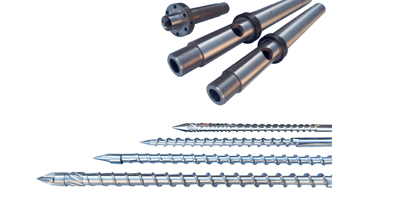
Screw Design and Function
Injection Unit Performance Parameters
Injection Capacity
Maximum volume of material that can be injected in one cycle, typically measured in cm³ or ounces
Injection Pressure
Maximum pressure applied to melt during injection, typically 1000-2000 bar
Injection Speed
Rate at which the screw moves forward during injection, in mm/s
Plasticizing Capacity
Amount of material melted per unit time, in kg/h
Design Consideration
The injection unit design must match the material characteristics and part requirements. Proper screw selection is critical for achieving optimal melt quality in any injection molding machine.
4. Clamping Unit Types and Structures
The clamping unit of an injection molding machine secures the mold during the injection and cooling phases, and facilitates mold opening and part ejection after cooling. Consistent clamping force is particularly critical when manufacturing precision components such as optical transceiver enclosures where dimensional accuracy is paramount.
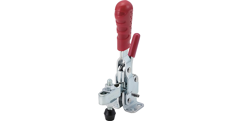
Toggle Clamping Mechanism
The toggle clamping system is widely used in modern injection molding machine designs for mold for injection molding machine. It uses a toggle linkage mechanism to multiply the force generated by a hydraulic cylinder. This design provides high clamping force with relatively low hydraulic pressure, offering energy efficiency and precise mold parallelism control.
Advantages of toggle systems include:
- Energy efficiency due to mechanical advantage
- Fast mold opening and closing speeds
- Positive mold locking at the end of the clamping stroke
- Reduced hydraulic oil requirements
Hydraulic Clamping Mechanism
Hydraulic clamping systems use direct-acting hydraulic cylinders to generate clamping force. While less common in modern injection molding machine models than toggle systems, they offer advantages for large machines and applications requiring high clamping forces. Hydraulic systems provide linear force development and are often simpler to maintain.
Electric Clamping Systems
In all-electric injection molding machine models, clamping force is generated by servo motors and ball screws or belt drives. These systems offer exceptional precision, energy efficiency, and control over clamping force and platen movement. Electric clamping provides precise position control and repeatability, making it ideal for precision molding applications.
Clamping Unit Components
Key components of any clamping unit include:
- Fixed platen (stationary, attached to machine frame)
- Moving platen (travels on tie bars to open/close mold)
- Tie bars (guide moving platen and resist clamping force)
- Ejection system (removes parts from mold after cooling)
- Safety guards and interlocks (protect operators during operation)
Clamping Mechanism Comparison
Clamping Force Calculation
The required clamping force for an injection molding machine depends on:
- Projected area of the part(s) and runners
- Injection pressure used
- Material characteristics
General Formula:
Clamping Force (tons) = (Projected Area (in²) × Injection Pressure (psi)) / 2000
A safety factor of 10-20% is typically added to the calculated value
Ejection System Types
Hydraulic Ejection
Powered by hydraulic cylinder, adjustable force and speed
Mechanical Ejection
Cam-driven, synchronized with mold opening
Electric Ejection
Servo motor driven, highly precise control
Pneumatic Ejection
Air-powered, for lightweight or small parts
5. Injection Molding Machine Specifications
Understanding injection molding machine specifications is essential for selecting the right equipment for specific manufacturing requirements.
Clamping Force
Clamping force, measured in tons (or kilonewtons), is one of the most critical specifications of an injection molding machine. It represents the maximum force the machine can exert to keep the mold closed during injection. Proper clamping force prevents flash (excess material) from forming between mold halves. Machines typically range from small benchtop or desktop injection molding machines with 10-50 tons of force to large industrial machines with 5,000+ tons of clamping force.
Injection Capacity
Injection capacity indicates the maximum volume of molten plastic that an injection molding machine can deliver in a single shot, typically measured in cubic centimeters (cm³) or ounces (oz). This specification determines the maximum part size that can be produced. It's generally recommended that the part weight be 40-80% of the machine's maximum injection capacity for optimal performance.
Platen Dimensions
Platen size specifications define the maximum mold dimensions that can be accommodated by the injection molding machine. Key measurements include:
- Platen width and height
- Minimum and maximum mold thickness
- Distance between tie bars (horizontal and vertical)
- Maximum mold opening stroke
Injection Pressure and Speed
Maximum injection pressure (measured in bar or psi) indicates the force the injection molding machine can apply to push molten plastic into the mold. This is critical for filling complex molds and achieving proper part density. Injection speed, measured in mm/s, determines how quickly the molten material is injected into the mold cavity, affecting part quality and cycle time.
Other Key Specifications
Additional important specifications include:
- Plasticizing capacity (kg/h of material melted)
- Ejection force and stroke
- Power consumption (kW)
- Machine dimensions and weight
- Maximum daylight (distance between platens when fully open)
Injection Molding Machine Size Categories
| Machine Category | Clamping Force | Injection Capacity | Typical Applications |
|---|---|---|---|
| Micro/Mini | 10-50 tons | 0.1-15 cm³ | Small components, electronics |
| Small | 50-200 tons | 15-100 cm³ | Consumer goods, small parts |
| Medium | 200-500 tons | 100-500 cm³ | Automotive parts, housings |
| Large | 500-2000 tons | 500-3000 cm³ | Large containers, panels |
| Extra Large | 2000+ tons | 3000+ cm³ | Automotive bumpers, large components |
Specification Matching Guidelines
- • Part weight should be 40-80% of machine capacity
- • Required clamping force = projected area × pressure × safety factor
- • Mold dimensions must fit within platen and tie bar constraints
- • Ensure adequate mold opening stroke for part ejection
6. Technical Conditions, Parameters and Standard Equipment
The technical conditions and parameters of an injection molding machine for sale define its operational capabilities and performance characteristics, while standard equipment ensures basic functionality.
Operating Temperature Ranges
An injection molding machine operates within specific temperature ranges that affect both machine performance and product quality:
- Barrel temperatures: Typically 150-350°C (300-660°F), depending on plastic material
- Mold temperatures: 20-150°C (68-300°F), controlled by temperature controllers
- Hydraulic oil temperature: 35-55°C (95-131°F) for optimal viscosity
- Ambient temperature: 10-40°C (50-104°F) for proper machine operation
Pressure Parameters
Various pressure parameters are critical to injection molding machine operation:
- Injection pressure: 500-2000 bar (7,250-29,000 psi)
- Hold pressure: Typically 30-70% of injection pressure
- Back pressure: 5-30 bar (70-435 psi) for melt homogenization
- Clamping pressure: Determined by clamping force and platen area
- Hydraulic system pressure: 100-180 bar (1,450-2,600 psi)
Cycle Time Components
The total cycle time of an injection molding machine consists of several components:
- Injection time: Time to fill the mold cavity (typically 1-5 seconds)
- Hold time: Pressure maintained to compensate for material shrinkage (2-10 seconds)
- Cooling time: Time for part to solidify in the mold (5-60+ seconds)
- Mold opening/closing time: Movement time for platens (2-10 seconds)
- Ejection time: Part removal time (1-5 seconds)
Standard Equipment
Every injection molding machine includes standard equipment for basic operation:
- Control panel with touchscreen interface
- Safety guards and interlock systems
- Hopper for material storage
- Barrel heater bands with temperature controllers
- Basic ejection system
- Hydraulic system with reservoir and filters (for hydraulic machines)
- Emergency stop buttons and safety features
Key Technical Parameters by Material Type
Advanced Control Features
Closed-Loop Control
Monitors and adjusts process variables in real-time for consistent part quality in injection molding machine operation
Process Monitoring
Tracks critical parameters throughout the cycle, providing data for process optimization
Recipe Storage
Stores multiple process parameter sets for quick changeover between different parts
Alarm Systems
Monitors for abnormal conditions and provides alerts for maintenance or process issues
Optional Equipment Enhancements
7. How to Select an Injection Molding Machine
Selecting the right injection molding machine involves careful consideration of part requirements, material characteristics, production volume, and budget constraints.
Determine Part Requirements
The first step in selecting an injection molding machine is to analyze the part specifications:
- Part dimensions and weight
- Material type and characteristics
- Required production volume and cycle time
- Precision and surface finish requirements
- Any special features (threads, inserts, undercuts)
Calculate Required Clamping Force
Proper clamping force is critical to prevent flash and ensure part quality. Calculate the required clamping force for your injection molding machine based on:
- Total projected area of the part(s) and runners (in square inches or square centimeters)
- Material's recommended injection pressure (typically 1000-2000 bar)
- A safety factor of 10-20% to account for variations
Evaluate Injection Capacity
The injection molding machine in used injection molding equipment must have sufficient injection capacity to produce the part in one shot. The part weight (including runners) should typically be 40-80% of the machine's maximum injection capacity. This range ensures proper plasticization while providing some flexibility for material variations or future part modifications.
Consider Machine Type
Select the appropriate injection molding machine type based on your specific needs:
- Horizontal vs. vertical configuration
- Hydraulic, electric, or hybrid drive system
- Specialized machines for unique applications
Evaluate Additional Requirements
Other factors to consider when selecting an injection molding machine include:
- Available floor space and installation requirements
- Energy consumption and utility requirements
- Automation capabilities and integration with auxiliary equipment
- Service and support availability from the manufacturer
- Budget constraints and total cost of ownership
- Future expansion or product line changes
Machine Selection Decision Tree
1. Part Analysis
Determine size, weight, material, and requirements
2. Calculate Minimum Requirements
Clamping force, shot size, platen size
3. Determine Machine Type
Horizontal/vertical, hydraulic/electric/hybrid
4. Evaluate Special Requirements
Automation, precision, cleanroom needs
5. Select Optimal Machine
Balance performance, cost, and future needs
Cost-Benefit Considerations
Selection Tips
- • Always test with your actual material and mold when possible
- • Consider future production needs when selecting machine size
- • Evaluate total cost of ownership, not just initial purchase price
- • Ensure adequate service and support is available locally
- • For complex parts, consult with injection molding machine specialists
8. Injection Molding Machine Repair Methods and Key Points
Proper repair techniques are essential for maintaining injection molding machine—a key type of injection molding equipment—performance, minimizing downtime, and extending equipment life.
Troubleshooting Common Issues
Effective injection molding machine repair begins with systematic troubleshooting:
- Identify symptoms and document all relevant details
- Check for error codes on the machine control panel
- Verify proper operation of safety interlocks
- Check for obvious issues (leaks, loose connections, damaged components)
- Consult machine manuals for diagnostic procedures
Hydraulic System Repairs
Hydraulic system issues are common in many injection molding machine models:
- Oil leaks: Replace worn seals, O-rings, and gaskets; tighten connections
- Pressure problems: Check and clean pressure relief valves; inspect pump performance
- Slow operation: Check for worn hydraulic cylinders; inspect flow control valves
- Contamination: Replace filters; flush system if necessary; check oil condition
Electrical System Repairs
Electrical issues require careful diagnosis and repair:
- Power problems: Check breakers, fuses, and power supply; inspect wiring for damage
- Sensor issues: Clean or replace faulty sensors; check alignment and connections
- Heater failures: Test heater elements and thermocouples; replace as needed
- Control system errors: Reset PLC; check for software updates; verify programming
Mechanical Component Repairs
Mechanical components of an injection molding machine require periodic repair:
- Screw and barrel wear: Inspect for scoring or damage; repair or replace as needed
- Toggle mechanism: Check for worn pins and bushings; lubricate and adjust
- Guide rails and tie bars: Clean, inspect for wear, and lubricate properly
- Ejection system: Adjust or replace worn ejector pins, plates, and bushings
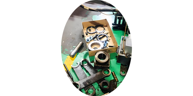
Repair Best Practices
Follow these key points for effective injection molding machine repairs:
- Use only genuine or recommended replacement parts
- Follow manufacturer specifications for torque, clearances, and adjustments
- Document all repairs, including parts replaced and adjustments made
- Test machine operation thoroughly before returning to production
- Analyze recurring issues to address root causes and prevent future failures
Common Failure Modes and Solutions
| Component | Common Issues | Repair Solution |
|---|---|---|
| Hydraulic Pump | Noise, reduced pressure | Replace worn bearings/seals; rebuild or replace pump |
| Injection Screw | Material degradation, pressure loss | Polish or replace screw; check for proper clearances |
| Heater Bands | Temperature fluctuations | Replace faulty heaters; check thermocouples |
| Toggle Mechanism | Uneven clamping, excessive wear | Replace worn pins/bushings; realign mechanism |
| Control System | Error codes, unresponsive controls | Reset system; update software; replace faulty modules |
Repair Safety Checklist
- Disconnect main power before electrical repairs
- Relieve all hydraulic pressure before hydraulic system work
- Allow components to cool before working on hot sections
- Use proper lockout/tagout procedures during all repairs
- Wear appropriate PPE for the repair task being performed
Repair Documentation
Maintain a detailed repair log for each injection molding machine including:
- Dates and descriptions of all repairs
- Parts replaced with part numbers
- Adjustments made and settings used
- Technician performing the work
- Test results after repair completion
