Injection Molding Machine Comprehensive Guide

Comprehensive Guide to Injection Molding Machines

A detailed overview of the technology, components, selection, and maintenance of modern injection molding equipment

1. Types and Characteristics of Injection Molding Machine

The injection molding machine—such as plastic injection molding machine—comes in various configurations, each designed to meet specific manufacturing requirements. Understanding these types is crucial for selecting the right equipment for your production needs.

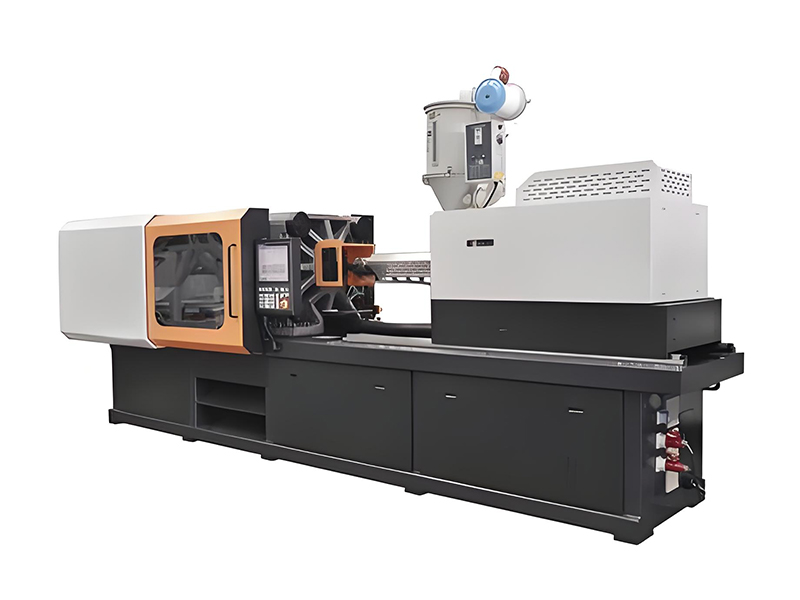
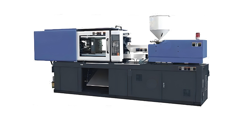
Horizontal Injection Molding Machine

The horizontal injection molding machine is the most common type, featuring a horizontal clamping unit and injection unit. This design allows for easy automation integration, efficient use of floor space, and simple operation. Horizontal machines are versatile and suitable for a wide range of applications from small components to large parts.

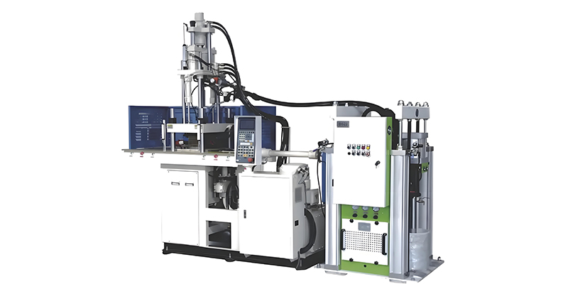
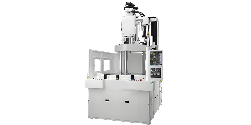
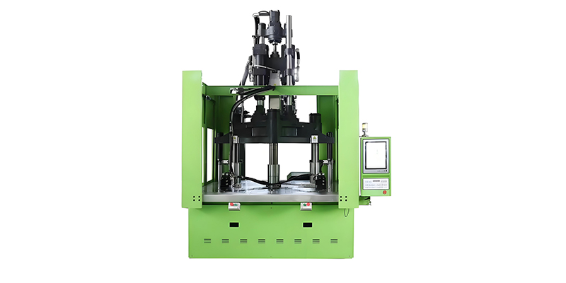
Vertical Injection Molding Machine

In vertical injection molding machine models, both the clamping and injection units are arranged vertically. This design offers advantages for insert molding applications, as gravity helps keep inserts in place. Vertical machines typically have a smaller footprint and are ideal for precision micro-molding and overmolding operations.

All-Electric Injection Molding Machine

All-electric injection molding machine systems use servo motors for all machine functions, eliminating the need for hydraulic systems. These machines offer superior precision, energy efficiency (up to 70% savings compared to hydraulic models), quieter operation, and faster cycle times. They are particularly suitable for cleanroom environments and applications requiring high repeatability.

Hybrid Injection Molding Machine

The hybrid injection molding machine combines the best features of hydraulic and electric systems, using electric motors for critical functions like injection and hydraulic systems for clamping. This results in a balance of precision, speed, and power, making hybrid machines a popular choice for many manufacturing environments seeking optimal performance with moderate energy consumption.

Different types of injection molding machines arranged in a manufacturing facility

Comparison of Injection Molding Machine Types

Machine Type Energy Efficiency Precision Typical Applications
Horizontal Hydraulic Moderate Good General purpose, large parts
Vertical Moderate Good Insert molding, micro-molding
All-Electric Excellent Excellent Precision parts, cleanroom
Hybrid Very Good Very Good Balanced performance needs

Specialized Injection Molding Machine Variants

  • Micro-injection molding machines for tiny precision components
  • Multi-material machines for complex part production
  • Stack mold machines for high-volume production
  • Low-pressure molding machines for sensitive electronics

2. Composition and Functions of Injection Molding Machine

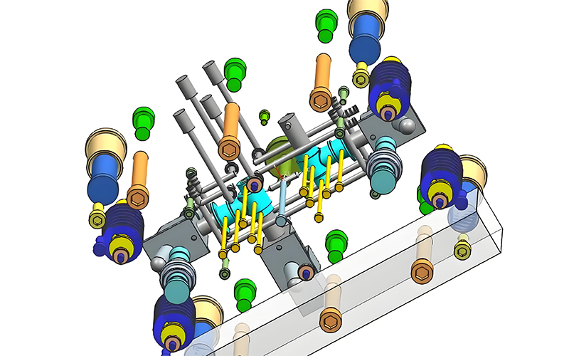
An injection molding machine—one of the essential injection molding machines—consists of several key components working together to transform plastic pellets into finished parts through the injection molding process.
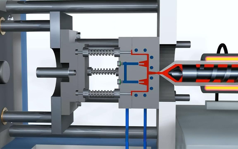
Injection Unit

The injection unit of an injection molding machine is responsible for melting, homogenizing, and delivering the plastic material into the mold. It includes the hopper, barrel, screw, heater bands, and nozzle. The screw rotates to convey, melt, and compress the plastic, while axial movement injects the molten material into the mold cavity.

Clamping Unit

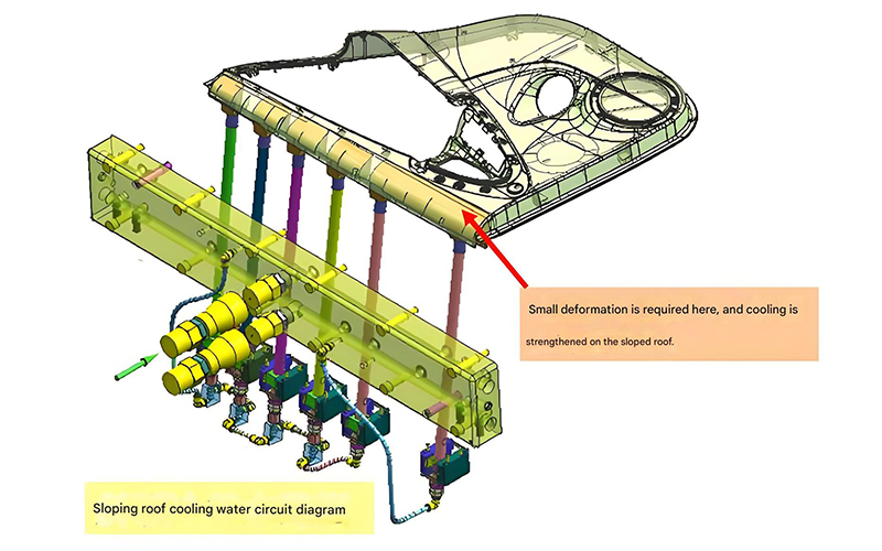
The clamping unit secures and opens the mold during the injection molding cycle. It consists of the fixed platen, moving platen, tie bars, and clamping mechanism (hydraulic, mechanical, or electric). The clamping force must be sufficient to keep the mold closed against the injection pressure generated by the injection molding machine.

Hydraulic System

In hydraulic injection molding machine models, the hydraulic system provides the power to operate both the injection and clamping units. It includes pumps, motors, valves, cylinders, and a reservoir. This system controls the speed, pressure, and position of moving components with high precision.

Electrical System

The electrical system controls all operations of the injection molding machine, including motor operation, heater control, sensor input processing, and sequence control. It comprises the control panel, programmable logic controller (PLC), servo motors (in electric and hybrid machines), sensors, and relays.

Control System

The control system acts as the "brain" of the injection molding machine, managing and coordinating all machine functions. Modern machines feature advanced touchscreen interfaces that allow operators to set parameters, monitor production, and store molding recipes. The control system ensures precise repeatability of each molding cycle.

Exploded view diagram showing the main components of an injection molding machine

Key Component Functions in an Injection Molding Machine

Auxiliary Components

Modern injection molding machine systems often include material dryers, loaders, mold temperature controllers, and robots for automated part removal and handling.

Interconnection System

All components communicate through the machine's network, ensuring synchronized operation during each phase of the injection molding cycle.

Performance Monitoring

Advanced sensors throughout the injection molding machine monitor temperature, pressure, speed, and position, providing real-time data to the control system for optimal performance.

3. Injection Unit Types and Structures

The injection unit is a critical component of any injection molding machine or injection mold machine, responsible for plasticizing and delivering molten material into the mold cavity.

Reciprocating Screw Injection Unit

The reciprocating screw design is the most common injection unit in modern injection molding machine models. This system combines plasticizing and injection functions in a single screw. During plasticization, the screw rotates to melt and convey material while moving backward to accumulate a shot. When injection begins, screw rotation stops, and the screw moves forward to inject the molten plastic into the mold.

Key components include:

  • Screw with three distinct zones: feed, compression, and metering
  • Barrel with heater bands for temperature control
  • Check ring or non-return valve to prevent backflow
  • Nozzle that connects to the mold sprue bushing

Plunger-Type Injection Unit

Plunger-type systems, found in older or smaller injection molding machine models, use a plunger to force material through a heated chamber. A separate plasticizing cylinder melts the material before it enters the injection chamber. While simpler in design, these units provide less uniform melt quality compared to reciprocating screw systems.

Specialized Injection Units

For specific applications, injection molding machine manufacturers offer specialized injection units:

  • Multi-stage screws for difficult-to-process materials
  • Accumulator injection units for high-speed, large-volume applications
  • Coinjection units for producing parts with multiple material layers
  • Micro-injection units for extremely small parts and precise shot control

Cross-sectional diagram of a reciprocating screw injection unit showing feed, compression, and metering zones

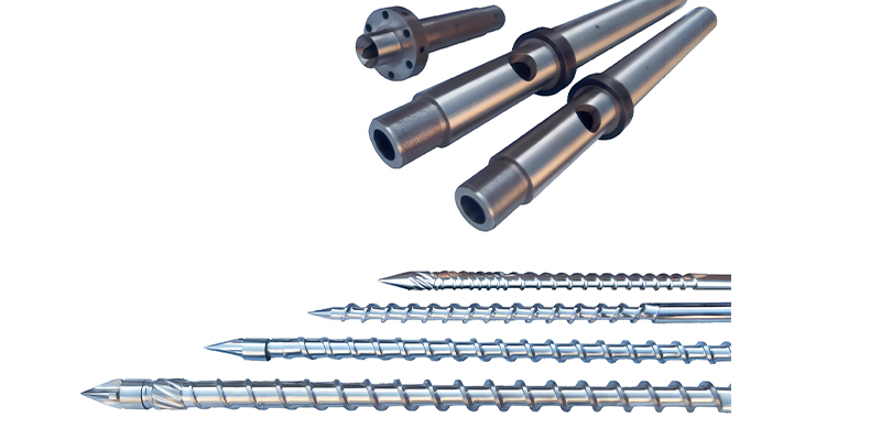
Screw Design and Function

Feed Zone (30-40% of length)
Compression Zone (30-40% of length)
Metering Zone (20-30% of length)

Injection Unit Performance Parameters

Injection Capacity

Maximum volume of material that can be injected in one cycle, typically measured in cm³ or ounces

Injection Pressure

Maximum pressure applied to melt during injection, typically 1000-2000 bar

Injection Speed

Rate at which the screw moves forward during injection, in mm/s

Plasticizing Capacity

Amount of material melted per unit time, in kg/h

Design Consideration

The injection unit design must match the material characteristics and part requirements. Proper screw selection is critical for achieving optimal melt quality in any injection molding machine.

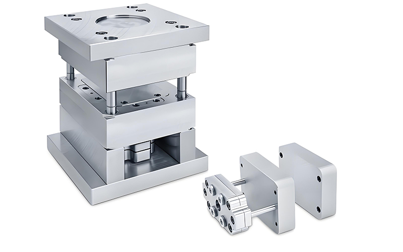
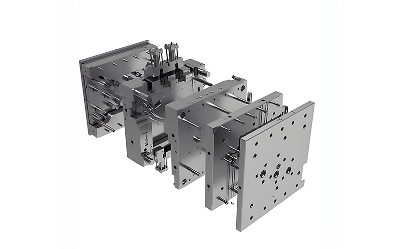
4. Clamping Unit Types and Structures

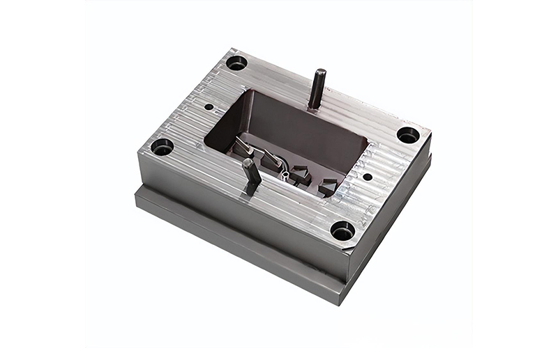
The clamping unit of an injection molding machine secures the mold during the injection and cooling phases, and facilitates mold opening and part ejection after cooling.

Toggle Clamping Mechanism

The toggle clamping system is widely used in modern injection molding machine designs for mold for injection molding machine. It uses a toggle linkage mechanism to multiply the force generated by a hydraulic cylinder. This design provides high clamping force with relatively low hydraulic pressure, offering energy efficiency and precise mold parallelism control.

Advantages of toggle systems include:

  • Energy efficiency due to mechanical advantage
  • Fast mold opening and closing speeds
  • Positive mold locking at the end of the clamping stroke
  • Reduced hydraulic oil requirements

Hydraulic Clamping Mechanism

Hydraulic clamping systems use direct-acting hydraulic cylinders to generate clamping force. While less common in modern injection molding machine models than toggle systems, they offer advantages for large machines and applications requiring high clamping forces. Hydraulic systems provide linear force development and are often simpler to maintain.

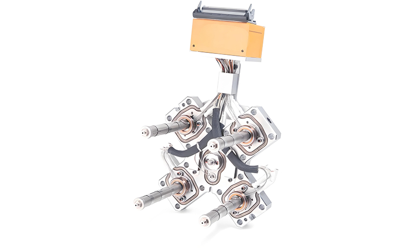
Electric Clamping Systems

In all-electric injection molding machine models, clamping force is generated by servo motors and ball screws or belt drives. These systems offer exceptional precision, energy efficiency, and control over clamping force and platen movement. Electric clamping provides precise position control and repeatability, making it ideal for precision molding applications.

Clamping Unit Components

Key components of any clamping unit include:

  • Fixed platen (stationary, attached to machine frame)
  • Moving platen (travels on tie bars to open/close mold)
  • Tie bars (guide moving platen and resist clamping force)
  • Ejection system (removes parts from mold after cooling)
  • Safety guards and interlocks (protect operators during operation)

Diagram showing toggle clamping mechanism operation in an injection molding machine

Clamping Mechanism Comparison

Clamping Force Calculation

The required clamping force for an injection molding machine depends on:

  • Projected area of the part(s) and runners
  • Injection pressure used
  • Material characteristics

General Formula:

Clamping Force (tons) = (Projected Area (in²) × Injection Pressure (psi)) / 2000

A safety factor of 10-20% is typically added to the calculated value

Ejection System Types

Hydraulic Ejection

Powered by hydraulic cylinder, adjustable force and speed

Mechanical Ejection

Cam-driven, synchronized with mold opening

Electric Ejection

Servo motor driven, highly precise control

Pneumatic Ejection

Air-powered, for lightweight or small parts

5. Injection Molding Machine Specifications

Understanding injection molding machine specifications is essential for selecting the right equipment for specific manufacturing requirements.

Clamping Force

Clamping force, measured in tons (or kilonewtons), is one of the most critical specifications of an injection molding machine. It represents the maximum force the machine can exert to keep the mold closed during injection. Proper clamping force prevents flash (excess material) from forming between mold halves. Machines typically range from small benchtop or desktop injection molding machines with 10-50 tons of force to large industrial machines with 5,000+ tons of clamping force.

Injection Capacity

Injection capacity indicates the maximum volume of molten plastic that an injection molding machine can deliver in a single shot, typically measured in cubic centimeters (cm³) or ounces (oz). This specification determines the maximum part size that can be produced. It's generally recommended that the part weight be 40-80% of the machine's maximum injection capacity for optimal performance.

Platen Dimensions

Platen size specifications define the maximum mold dimensions that can be accommodated by the injection molding machine. Key measurements include:

  • Platen width and height
  • Minimum and maximum mold thickness
  • Distance between tie bars (horizontal and vertical)
  • Maximum mold opening stroke
These dimensions determine the maximum part size and mold configuration possible with the machine.

Injection Pressure and Speed

Maximum injection pressure (measured in bar or psi) indicates the force the injection molding machine can apply to push molten plastic into the mold. This is critical for filling complex molds and achieving proper part density. Injection speed, measured in mm/s, determines how quickly the molten material is injected into the mold cavity, affecting part quality and cycle time.

Other Key Specifications

Additional important specifications include:

  • Plasticizing capacity (kg/h of material melted)
  • Ejection force and stroke
  • Power consumption (kW)
  • Machine dimensions and weight
  • Maximum daylight (distance between platens when fully open)

Technical specification chart showing various injection molding machine models and their key parameters

Injection Molding Machine Size Categories

Machine Category Clamping Force Injection Capacity Typical Applications
Micro/Mini 10-50 tons 0.1-15 cm³ Small components, electronics
Small 50-200 tons 15-100 cm³ Consumer goods, small parts
Medium 200-500 tons 100-500 cm³ Automotive parts, housings
Large 500-2000 tons 500-3000 cm³ Large containers, panels
Extra Large 2000+ tons 3000+ cm³ Automotive bumpers, large components
Specification Matching Guidelines
  • • Part weight should be 40-80% of machine capacity
  • • Required clamping force = projected area × pressure × safety factor
  • • Mold dimensions must fit within platen and tie bar constraints
  • • Ensure adequate mold opening stroke for part ejection

6. Technical Conditions, Parameters and Standard Equipment

The technical conditions and parameters of an injection molding machine for sale define its operational capabilities and performance characteristics, while standard equipment ensures basic functionality.

Operating Temperature Ranges

An injection molding machine operates within specific temperature ranges that affect both machine performance and product quality:

  • Barrel temperatures: Typically 150-350°C (300-660°F), depending on plastic material
  • Mold temperatures: 20-150°C (68-300°F), controlled by temperature controllers
  • Hydraulic oil temperature: 35-55°C (95-131°F) for optimal viscosity
  • Ambient temperature: 10-40°C (50-104°F) for proper machine operation
Maintaining these temperatures within specified ranges is critical for consistent production and equipment longevity.

Pressure Parameters

Various pressure parameters are critical to injection molding machine operation:

  • Injection pressure: 500-2000 bar (7,250-29,000 psi)
  • Hold pressure: Typically 30-70% of injection pressure
  • Back pressure: 5-30 bar (70-435 psi) for melt homogenization
  • Clamping pressure: Determined by clamping force and platen area
  • Hydraulic system pressure: 100-180 bar (1,450-2,600 psi)
These pressures are precisely controlled by the machine's hydraulic or electric systems to ensure proper filling, packing, and cooling of molded parts.

Cycle Time Components

The total cycle time of an injection molding machine consists of several components:

  • Injection time: Time to fill the mold cavity (typically 1-5 seconds)
  • Hold time: Pressure maintained to compensate for material shrinkage (2-10 seconds)
  • Cooling time: Time for part to solidify in the mold (5-60+ seconds)
  • Mold opening/closing time: Movement time for platens (2-10 seconds)
  • Ejection time: Part removal time (1-5 seconds)
Total cycle times can range from 5 seconds for small parts to several minutes for large or thick-walled components.

Standard Equipment

Every injection molding machine includes standard equipment for basic operation:

  • Control panel with touchscreen interface
  • Safety guards and interlock systems
  • Hopper for material storage
  • Barrel heater bands with temperature controllers
  • Basic ejection system
  • Hydraulic system with reservoir and filters (for hydraulic machines)
  • Emergency stop buttons and safety features

Injection molding machine control panel showing technical parameters and settings

Key Technical Parameters by Material Type

Advanced Control Features

Closed-Loop Control

Monitors and adjusts process variables in real-time for consistent part quality in injection molding machine operation

Process Monitoring

Tracks critical parameters throughout the cycle, providing data for process optimization

Recipe Storage

Stores multiple process parameter sets for quick changeover between different parts

Alarm Systems

Monitors for abnormal conditions and provides alerts for maintenance or process issues

Optional Equipment Enhancements
Material drying systems
Robot integration
Extended hopper systems
Barrel insulation
Core pull hydraulic circuits
Energy monitoring systems

7. How to Select an Injection Molding Machine

Selecting the right injection molding machine involves careful consideration of part requirements, material characteristics, production volume, and budget constraints.

Determine Part Requirements

The first step in selecting an injection molding machine is to analyze the part specifications:

  • Part dimensions and weight
  • Material type and characteristics
  • Required production volume and cycle time
  • Precision and surface finish requirements
  • Any special features (threads, inserts, undercuts)
These factors will determine the minimum requirements for machine size, clamping force, and injection capacity.

Calculate Required Clamping Force

Proper clamping force is critical to prevent flash and ensure part quality. Calculate the required clamping force for your injection molding machine based on:

  • Total projected area of the part(s) and runners (in square inches or square centimeters)
  • Material's recommended injection pressure (typically 1000-2000 bar)
  • A safety factor of 10-20% to account for variations
The formula is: Clamping Force (tons) = (Projected Area × Injection Pressure) / Conversion Factor

Evaluate Injection Capacity

The injection molding machine in used injection molding equipment must have sufficient injection capacity to produce the part in one shot. The part weight (including runners) should typically be 40-80% of the machine's maximum injection capacity. This range ensures proper plasticization while providing some flexibility for material variations or future part modifications.

Consider Machine Type

Select the appropriate injection molding machine type based on your specific needs:

  • Horizontal vs. vertical configuration
  • Hydraulic, electric, or hybrid drive system
  • Specialized machines for unique applications
All-electric machines offer advantages in precision and energy efficiency, while hydraulic machines may be more cost-effective for certain high-force applications.

Evaluate Additional Requirements

Other factors to consider when selecting an injection molding machine include:

  • Available floor space and installation requirements
  • Energy consumption and utility requirements
  • Automation capabilities and integration with auxiliary equipment
  • Service and support availability from the manufacturer
  • Budget constraints and total cost of ownership
  • Future expansion or product line changes

Flowchart showing the injection molding machine selection process

Machine Selection Decision Tree

1. Part Analysis

Determine size, weight, material, and requirements

2. Calculate Minimum Requirements

Clamping force, shot size, platen size

3. Determine Machine Type

Horizontal/vertical, hydraulic/electric/hybrid

4. Evaluate Special Requirements

Automation, precision, cleanroom needs

5. Select Optimal Machine

Balance performance, cost, and future needs

Cost-Benefit Considerations

Selection Tips
  • • Always test with your actual material and mold when possible
  • • Consider future production needs when selecting machine size
  • • Evaluate total cost of ownership, not just initial purchase price
  • • Ensure adequate service and support is available locally
  • • For complex parts, consult with injection molding machine specialists

8. Injection Molding Machine Repair Methods and Key Points

Proper repair techniques are essential for maintaining injection molding machine—a key type of injection molding equipment—performance, minimizing downtime, and extending equipment life.

Troubleshooting Common Issues

Effective injection molding machine repair begins with systematic troubleshooting:

  • Identify symptoms and document all relevant details
  • Check for error codes on the machine control panel
  • Verify proper operation of safety interlocks
  • Check for obvious issues (leaks, loose connections, damaged components)
  • Consult machine manuals for diagnostic procedures
A structured approach helps isolate the root cause rather than just addressing symptoms.

Hydraulic System Repairs

Hydraulic system issues are common in many injection molding machine models:

  • Oil leaks: Replace worn seals, O-rings, and gaskets; tighten connections
  • Pressure problems: Check and clean pressure relief valves; inspect pump performance
  • Slow operation: Check for worn hydraulic cylinders; inspect flow control valves
  • Contamination: Replace filters; flush system if necessary; check oil condition
Always follow proper safety procedures when working with hydraulic systems, including relieving pressure before disassembly.

Electrical System Repairs

Electrical issues require careful diagnosis and repair:

  • Power problems: Check breakers, fuses, and power supply; inspect wiring for damage
  • Sensor issues: Clean or replace faulty sensors; check alignment and connections
  • Heater failures: Test heater elements and thermocouples; replace as needed
  • Control system errors: Reset PLC; check for software updates; verify programming
Electrical repairs should only be performed by qualified technicians following lockout/tagout procedures.

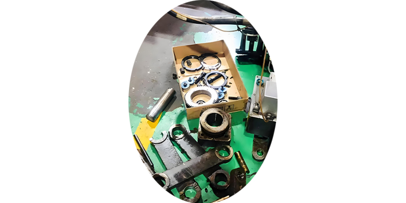
Mechanical Component Repairs

Mechanical components of an injection molding machine require periodic repair:

  • Screw and barrel wear: Inspect for scoring or damage; repair or replace as needed
  • Toggle mechanism: Check for worn pins and bushings; lubricate and adjust
  • Guide rails and tie bars: Clean, inspect for wear, and lubricate properly
  • Ejection system: Adjust or replace worn ejector pins, plates, and bushings
Proper reassembly and alignment are critical for mechanical repairs to ensure optimal performance and prevent premature wear.

Repair Best Practices

Follow these key points for effective injection molding machine repairs:

  • Use only genuine or recommended replacement parts
  • Follow manufacturer specifications for torque, clearances, and adjustments
  • Document all repairs, including parts replaced and adjustments made
  • Test machine operation thoroughly before returning to production
  • Analyze recurring issues to address root causes and prevent future failures

Technician performing maintenance on injection molding machine hydraulic system

Common Failure Modes and Solutions

Component Common Issues Repair Solution
Hydraulic Pump Noise, reduced pressure Replace worn bearings/seals; rebuild or replace pump
Injection Screw Material degradation, pressure loss Polish or replace screw; check for proper clearances
Heater Bands Temperature fluctuations Replace faulty heaters; check thermocouples
Toggle Mechanism Uneven clamping, excessive wear Replace worn pins/bushings; realign mechanism
Control System Error codes, unresponsive controls Reset system; update software; replace faulty modules

Repair Safety Checklist

  • Disconnect main power before electrical repairs
  • Relieve all hydraulic pressure before hydraulic system work
  • Allow components to cool before working on hot sections
  • Use proper lockout/tagout procedures during all repairs
  • Wear appropriate PPE for the repair task being performed
Repair Documentation

Maintain a detailed repair log for each injection molding machine including:

  • Dates and descriptions of all repairs
  • Parts replaced with part numbers
  • Adjustments made and settings used
  • Technician performing the work
  • Test results after repair completion

9. Injection Molding Machine Maintenance and Servicing

Regular maintenance is essential for maximizing injection molding machine and support machinery performance, reducing downtime, and extending equipment lifespan.

Preventive Maintenance Program

A structured preventive maintenance program for your injection molding machine should include:

  • Daily inspections and checks
  • Weekly maintenance tasks
  • Monthly inspections and adjustments
  • Quarterly in-depth maintenance
  • Annual comprehensive servicing
Following the manufacturer's recommended maintenance schedule ensures all critical components receive proper attention.

Daily Maintenance Tasks

Daily maintenance for an injection molding machine should include:

  • Check hydraulic oil level and condition
  • Inspect for oil leaks in hydraulic system
  • Verify proper operation of safety devices
  • Clean machine surfaces and remove debris
  • Check heater band operation and temperatures
  • Inspect hopper for material level and contamination
  • Record any unusual noises, vibrations, or performance issues
These quick checks help identify potential issues before they escalate into major problems.

Periodic Maintenance Activities

Regular scheduled maintenance for your injection molding machine includes:

  • Lubrication of moving parts according to specifications
  • Hydraulic fluid analysis and replacement
  • Filter replacements (hydraulic, air, oil)
  • Alignment checks of platens and tie bars
  • Screw and barrel inspection for wear
  • Electrical connection checks and tightening
  • Calibration of sensors and control systems
The frequency of these tasks depends on machine usage, operating conditions, and manufacturer recommendations.

Long-Term Maintenance Strategies

Effective long-term maintenance for an injection molding machine includes:

  • Developing a comprehensive maintenance schedule and checklist
  • Training personnel on proper maintenance procedures
  • Maintaining a complete inventory of critical spare parts
  • Documenting all maintenance activities and machine performance
  • Planning for major overhauls based on machine hours and performance
  • Regularly reviewing and updating maintenance procedures
  • Considering predictive maintenance technologies for critical components
  • Related Hydraulic Spare Parts

Maintenance technician performing scheduled service on an injection molding machine

Maintenance Schedule Overview

Daily
  • • Visual inspection for leaks and damage
  • • Check fluid levels and temperatures
  • • Verify safety systems operation
Weekly
  • • Lubricate moving components
  • • Clean filters and cooling systems
  • • Check alignment of critical components
Monthly
  • • Inspect hydraulic components
  • • Check heater bands and thermocouples
  • • Test safety interlocks thoroughly
Annually
  • • Complete fluid change and system flush
  • • Major component inspection and measurement
  • • Control system calibration and updates
Benefits of Proper Maintenance
Higher productivity
Reduced downtime
Better part quality
Lower repair costs
Longer machine life
Fewer safety incidents

Comprehensive Injection Mold Engineering Guide

A complete technical reference covering the entire lifecycle of an injection mold, from design through validation and production implementation.

1. Injection Mold Structure and Classification

The serves as the fundamental tool in plastic manufacturing, transforming molten polymer into precise, repeatable parts. A standard injection mold comprises two primary assemblies: the stationary platen (fixed half) and the moving platen (ejector half), which work in tandem during the molding cycle.

The stationary half, mounted to the injection unit, contains the sprue bushing that interfaces with the machine nozzle, delivering molten plastic into the mold. This half typically houses the cavity inserts when producing external part geometries. The moving half attaches to the clamping unit and contains core inserts that form internal part features, along with the ejection system responsible for part removal after molding.

When the molding machine clamps the injection mold, these two halves create a sealed cavity where plastic solidifies. Guide pins and bushings ensure precise alignment during each cycle, maintaining dimensional accuracy across thousands or millions of parts.

Primary Classification Systems

By Cavity Configuration:

  • Single-cavity molds: Produce one part per cycle, ideal for large components or low-volume production
  • Multi-cavity molds: Create multiple identical parts simultaneously, improving production efficiency for high-volume items
  • Family molds: Produce different components in a single cycle, useful for assembly sets

By Construction Type:

  • Two-plate molds: Simplest design with one parting line, featuring a direct sprue-gate system
  • Three-plate molds: Incorporate an additional parting line to automatically separate runners from parts
  • Stack molds: Utilize multiple parting surfaces in a vertical stack, doubling or tripling output without increasing machine size
  • Unscrewing molds: Include mechanical or hydraulic systems to rotate and extract threaded components

By Runner System:

  • Cold runner molds: Feature cooled channels that solidify with the part, requiring runner removal
  • Hot runner molds: Maintain molten plastic in heated manifolds, eliminating runner waste and reducing cycle time

The selection of injection mold type depends on production volume, part complexity, material properties, and cost considerations. High-volume applications typically benefit from multi-cavity or hot runner molds, while low-volume or prototype production may use simpler, less expensive designs.

Two-Plate Injection Mold Structure

Cross-sectional diagram of a two-plate injection mold showing stationary and moving halves, cavity, core, sprue, runner system, and ejection mechanism

Key components: 1. Sprue bushing 2. Cavity plate 3. Core plate 4. Ejector pins 5. Guide pins 6. Cooling channels

Injection Mold Classification Comparison

2. Injection Mold Material Selection

Material selection for an injection mold—including aluminum molds for injection molding—directly impacts performance, durability, and cost. The ideal material must balance hardness, toughness, wear resistance, corrosion resistance, and thermal conductivity while meeting production volume requirements and part quality specifications.

Base materials for injection mold components are selected based on several critical factors: expected production volume, plastic material being processed, part complexity and surface finish requirements, molding temperature, and cost constraints.

Common Mold Materials

Pre-hardened Steels (28-35 HRC):

These are the most commonly used materials for injection mold construction, offering a balance of machinability and durability. Examples include:

  • 718H (ASSAB): A nickel-chromium-molybdenum alloy with excellent polishability and machinability, suitable for 100,000-500,000 cycles
  • P20 (AISI): A general-purpose mold steel with good toughness and wear resistance, ideal for moderate production runs
  • NAK80: A pre-hardened plastic mold steel with superior polishability, often used for parts requiring high surface finish without additional heat treatment

Hardened Steels (45-55 HRC):

Used for high-volume production or when processing abrasive materials that would quickly wear softer steels:

  • S136 (ASSAB): A corrosion-resistant stainless steel with excellent polishability, ideal for processing PVC or other corrosive materials
  • H13 (AISI): A hot-work tool steel with exceptional thermal shock resistance, suitable for high-temperature engineering resins
  • STAVAX: A premium stainless steel offering superior corrosion resistance and polishability for medical or cleanroom applications

Specialty Materials:

  • Aluminum alloys (7075, 6061): Used for prototype molds or low-volume production, offering faster cooling and reduced machining time
  • Copper alloys: Employed in areas requiring enhanced thermal conductivity for improved cooling efficiency
  • Carbide inserts: Used in high-wear areas for extreme production volumes or highly abrasive materials

Material selection for the injection mold directly influences tooling cost and longevity. Pre-hardened steels offer lower initial costs and faster production, while hardened steels provide extended mold life at a higher upfront investment. For critical applications, a hybrid approach may be used, with hardened steel inserts in high-wear areas combined with pre-hardened steel for less critical components.

Mold Material Properties Comparison

Material Hardness (HRC) Typical Cycle Life Corrosion Resistance Polishability
P20 28-32 100,000-500,000 Low Moderate
718H 33-37 500,000-1,000,000 Low High
NAK80 38-42 500,000-1,000,000 Moderate Excellent
S136 48-52 1,000,000+ Excellent Excellent
Aluminum 7075 15-19 10,000-50,000 Moderate High

Material Selection Decision Tree

Flowchart showing decision process for selecting injection mold materials based on production volume, material type, and surface requirements

3. Mold Base Specification Selection

The mold base forms the foundation of any injection mold—a core component of molds for plastic injection—providing structural support for cavity and core inserts, guiding movement between mold halves, and housing auxiliary systems. Proper selection of mold base specifications ensures dimensional stability, alignment accuracy, and adequate support for all injection mold components during the repeated stresses of production.

Mold bases are typically standardized according to industry specifications from organizations like DME, Hasco, or LKM, with custom modifications for specific applications. Key considerations in mold base selection include size, material, guide system, and plate thickness.

Mold Base Selection Criteria

Size and Dimensions: The mold base must provide sufficient space for cavities, cores, runner systems, cooling channels, and ejection mechanisms while fitting within the molding machine's platens. Critical dimensions include:

  • Overall length, width, and height
  • Distance between tie bars (must fit within machine specifications)
  • Platen thickness and maximum daylight opening
  • Minimum and maximum mold height for the target machine

Material Selection: Mold base plates are typically constructed from:

  • S50C or 1.1730 carbon steel for standard applications
  • Pre-hardened steels for higher durability requirements
  • Stainless steel for corrosive environments

Guide System: Precision alignment is critical for injection mold performance. Guide systems include:

  • Guide pins and bushings: Standard for most applications
  • Ball bearings or roller guides: For large molds or high-precision requirements
  • Leader pins: Additional alignment for三板模 designs

Plate Configuration: The number and arrangement of plates depend on mold complexity:

  • A-plate and B-plate for two-plate molds
  • Additional runner plates for three-plate molds
  • Ejector plates, support plates, and spacer blocks for ejection system accommodation

Standard vs. Custom: While standard mold bases offer cost and lead time advantages, custom mold bases may be required for:

  • Very large or unusually shaped parts
  • Specialized cooling requirements
  • Integration with hot runner systems
  • Multi-material or overmolding applications

Proper mold base selection for an injection mold requires close coordination between mold designers, part designers, and production engineers to ensure compatibility with both the part requirements and the target molding equipment. A well-selected mold base contributes significantly to mold longevity, part quality consistency, and overall production efficiency.

Mold Base Components

Exploded view diagram of a standard injection mold base showing all components including A-plate, B-plate, ejector plate, support plate, guide pins, bushings, and tie bars

1. Top clamping plate 2. A-plate 3. B-plate 4. Support plate 5. Ejector plate 6. Ejector retainer plate 7. Bottom clamping plate 8. Guide pins 9. Guide bushings

Mold Base Sizing Chart

4. Mold Cavity and Core Design

The cavity and core represent the heart of any injection mold, directly shaping the plastic part. These critical components—central to injection mold design—must be designed with meticulous attention to detail, considering part geometry, material behavior, cooling requirements, and manufacturing constraints. The cavity forms the external surfaces of the part, while the core creates internal features and determines the part's overall dimensions.

Effective cavity and core design for an injection mold requires balancing functional requirements with manufacturability, ensuring both part quality and mold longevity.

Key Design Considerations

Part Shrinkage Allowance: All plastics shrink as they cool, requiring the injection mold cavity and core to be oversized accordingly. Shrinkage rates vary by material (typically 0.5-2% for most thermoplastics) and must be precisely calculated and incorporated into the design. Factors affecting shrinkage include:

  • Material type and grade
  • Wall thickness distribution
  • Molding temperature and pressure
  • Cooling rate and uniformity

Wall Thickness: Maintaining uniform wall thickness throughout the part minimizes warpage and ensures consistent filling and cooling. The cavity and core design must accommodate:

  • Minimum thickness based on material flow properties
  • Maximum thickness to avoid sink marks and prolonged cooling
  • Gradual transitions between thickness changes

Draft Angles: All vertical surfaces in the cavity and core require draft angles to facilitate part ejection and prevent damage. Proper draft angles depend on:

  • Surface finish requirements (higher polish needs less draft)
  • Material type (amorphous vs. crystalline polymers)
  • Part height and complexity
  • Typical draft angles range from 0.5° to 3° per side

Undercuts and Complex Features: Features that prevent straight-line ejection require special injection mold mechanisms:

  • Side cores or slides for external undercuts
  • Lifters for internal undercuts
  • Collapsible cores for complex internal geometries
  • Unscrewing mechanisms for threaded features

Insert Design: Cavity and core inserts should be designed for:

  • Easy replacement for wear or modification
  • Secure mounting with proper locating and fastening
  • Adequate support to prevent deflection under injection pressure
  • Integration with cooling channels

Modern injection mold cavity and core design leverages advanced CAD/CAM systems and simulation software to optimize geometry, predict potential issues, and ensure manufacturability. This digital approach allows for virtual testing of different designs, reducing the need for physical prototypes and accelerating the development process while improving final part quality.

Cavity and Core Design Elements

Cross-sectional view showing cavity and core relationship in an injection mold with proper draft angles, wall thickness, and cooling channels

Proper Draft

0.5°-3° angles on vertical surfaces for easy ejection

Uniform Walls

Consistent thickness to prevent warpage and sink marks

Radiused Corners

Improves material flow and reduces stress concentrations

Cooling Channels

Strategically placed for uniform cooling and reduced cycle time

Undercut Solutions

5. Gating and Runner System

The gating and runner system in injection mold tooling serves as the conduit through which molten plastic flows from the machine nozzle to the mold cavity. Proper design of this system is critical for achieving uniform filling, minimizing pressure loss, controlling part quality, and reducing material waste. The efficiency of the gating and runner system directly impacts injection mold performance, cycle time, and overall production economics.

Runner System Design

Runners are the channels that distribute molten plastic from the sprue to the gates. Key design considerations include:

  • Cross-sectional geometry: Circular cross-sections are most efficient (lowest pressure drop), while trapezoidal or rectangular shapes are easier to machine
  • Size: Must be sufficient to maintain melt temperature and pressure while minimizing material waste
  • Layout: Balanced for multi-cavity molds to ensure uniform filling of all cavities
  • Length: Kept as short as possible to reduce pressure loss and material usage

Common runner configurations include:

  • Radial (star) layout: Central sprue with runners radiating to each cavity
  • H-layout: For rectangular part arrangements
  • Tree layout: For complex, irregular cavity arrangements
  • Hot runner systems: Maintain molten plastic in heated manifolds, eliminating runner waste

Gating Design

The gate is the final orifice through which plastic enters the cavity, controlling flow rate, pressure, and cooling behavior. Gate design considerations include:

  • Location: Should facilitate proper filling, avoid weld lines in critical areas, and allow easy gate removal
  • Size: Determines fill rate and pressure; smaller gates create shear heating but may cause hesitation
  • Type: Selected based on material, part geometry, and appearance requirements

Common gate types for injection mold applications:

  • Edge gate: Simple, economical, suitable for most applications
  • Submarine (tunnel) gate: Automatically shears from part, suitable for automation
  • Pin gate: Creates small gate marks, used for cosmetic parts
  • Hot tip gate: For hot runner systems, minimal gate vestige
  • Diaphragm gate: For cylindrical parts, creates uniform flow
  • Film gate: For large, flat parts, provides wide flow front
  • Valve gate: Controlled by mechanical or hydraulic pins, allows precise timing control

Modern injection mold design utilizes computer-aided engineering (CAE) software to simulate flow through the runner and gate system, optimizing design parameters before mold fabrication. This simulation helps identify potential issues such as air traps, weld lines, and uneven filling, allowing for design refinement that improves part quality and reduces development time.

Runner and Gate Configurations

Various runner system layouts and gate types used in injection molds including edge gates, pin gates, submarine gates, and hot runner systems
Edge Gate Pin Gate Submarine Gate Hot Runner Film Gate

Gate Selection Criteria

6. Mold Cooling System

The cooling system is a critical set of injection molding mold parts in any injection mold, responsible for extracting heat from the molten plastic to solidify the part. Efficient cooling directly impacts cycle time, part quality, and dimensional stability. In fact, the cooling phase typically accounts for 50-70% of the total molding cycle, making it a primary focus for optimizing injection mold performance and production efficiency.

An effective cooling system must maintain uniform temperature distribution throughout the mold, preventing warpage, shrinkage variations, and surface defects while minimizing cycle time.

Cooling System Design Principles

Channel Layout: Cooling channels should follow the contour of the part as closely as possible, maintaining a consistent distance (typically 1.5-2.5 times the channel diameter) from the cavity surface. Key considerations include:

  • Uniform spacing to ensure consistent cooling rates
  • Adequate coverage of all part areas, especially thick sections
  • Balanced flow distribution to all cooling circuits
  • Avoidance of interference with other mold components

Channel Sizing: Properly sized cooling channels ensure turbulent flow, which provides significantly better heat transfer than laminar flow. Design parameters include:

  • Diameter: Typically 6-12mm for standard applications
  • Length: Should not exceed 50 times the channel diameter
  • Flow rate: Sufficient to maintain Reynolds number above 4000 (turbulent flow)
  • Pressure drop: Kept within acceptable limits (typically <5 bar)

Circuit Configuration: Cooling circuits can be arranged in various configurations:

  • Series circuits: Simple but may create temperature gradients
  • Parallel circuits: Better temperature uniformity with proper balancing
  • Series-parallel combinations: For complex part geometries
  • Conformal cooling: 3D-printed channels that exactly follow part contours

Cooling Media and Control: The choice of cooling medium and its temperature control affect system performance:

  • Water: Most common, excellent heat transfer properties
  • Water-glycol mixtures: For lower temperature requirements
  • Oil: For high-temperature applications (above 100°C)
  • Precision temperature controllers: Maintain ±1°C stability
  • Flow meters: Monitor and verify cooling circuit performance

Advanced injection mold cooling systems may incorporate specialized features such as bubblers, baffles, and thermally conductive inserts to address challenging geometries. Computational fluid dynamics (CFD) analysis is increasingly used to optimize cooling system design, simulating flow patterns and temperature distribution to identify and correct potential issues before mold fabrication.

Cooling System Configurations

Various cooling channel configurations in injection molds including parallel circuits, series circuits, baffles, bubblers, and conformal cooling channels

Parallel Circuits

Uniform flow distribution for consistent cooling

Series Circuits

Simpler design with potential temperature gradients

Baffles & Bubblers

Effective cooling for deep or thick sections

Conformal Cooling

3D-printed channels following part contours

Cooling Efficiency Metrics

7. Ejection and Reset Mechanism

The ejection system of injection molds is responsible for safely and efficiently removing the solidified part from the mold cavity after cooling. A well-designed ejection system ensures minimal part deformation, no damage to critical surfaces, and reliable operation throughout the injection mold's service life. The reset mechanism then returns these components to their starting position in preparation for the next molding cycle.

Ejection systems must overcome the part's adhesion to the mold surfaces, which results from several factors including vacuum forces, mechanical interlock, and thermal contraction. The design must apply sufficient force to overcome these factors while distributing that force evenly to prevent part damage.

Ejection System Components

Primary Ejection Methods: The choice of ejection method depends on part geometry, material properties, and surface finish requirements:

  • Ejector pins: Most common, simple, economical solution for many applications
  • Ejector sleeves: Used for cylindrical features or around cores
  • Ejector plates/blocks: For large, flat surfaces requiring uniform force distribution
  • Blade ejectors: For thin-walled parts or where minimal witness marks are required
  • Lifters: For parts with undercuts that prevent straight-line ejection
  • Air ejection: Uses compressed air to assist or replace mechanical ejection
  • Unscrewing mechanisms: For threaded parts requiring rotational ejection

Ejection System Design Considerations:

  • Force distribution: Ejection points should be placed to minimize part distortion
  • Witness marks: Ejector locations should avoid critical cosmetic surfaces when possible
  • Stroke length: Must be sufficient to completely remove the part from the mold
  • Speed and timing: Ejection should be synchronized with mold opening
  • Guidance: Ejector plates should be properly guided to prevent binding
  • Return: Reliable mechanism to reset ejectors to starting position

Reset Mechanisms: After ejection, the system must return to its original position:

  • Return pins: Contact the stationary platen during mold closing to reset ejectors
  • Return springs: Provide force to retract ejectors
  • Hydraulic or pneumatic cylinders: For complex ejection sequences
  • Limit switches: Ensure proper reset position before mold closing

Modern injection mold ejection systems often incorporate sensors to verify proper part ejection, preventing mold damage from misaligned or stuck parts. Sequential ejection may be used for complex parts, with multiple ejection stages occurring in a predetermined order to safely release the part from the mold.

Ejection System Components

Exploded view of injection mold ejection system showing ejector pins, ejector plate, retainer plate, return pins, springs, and guide bushings

1. Ejector pins 2. Ejector plate 3. Ejector retainer plate 4. Return pins 5. Compression springs 6. Ejector guide pins 7. Ejector guide bushings

Ejection Method Comparison

8. Mold Hot Runner System

A hot runner system is an advanced component in modern injection mold technology and injection molding tooling that maintains molten plastic in the runner system during the molding cycle, eliminating the production of solidified runner waste. This technology offers significant advantages in terms of material utilization, cycle time reduction, and part quality improvement, making it a valuable investment for high-volume injection mold applications.

Hot runner systems replace the traditional cold runner system with heated manifolds and nozzles that keep the plastic in a molten state throughout the molding process. This allows for precise control over the flow of plastic into the mold cavities, resulting in more consistent part quality and reduced material waste.

Hot Runner System Components

Manifolds: The central distribution component that delivers molten plastic to each nozzle:

  • Constructed from heat-treated tool steel for durability
  • Internal flow channels precisely machined for balanced flow
  • Heated with cartridge heaters or heater bands
  • Thermally insulated from the rest of the mold

Nozzles: Deliver molten plastic from the manifold to the mold cavity:

  • Tip styles vary based on application (open, valve-gated, etc.)
  • Individually heated for precise temperature control
  • Available in various lengths and configurations
  • Designed to minimize shear heating and material degradation

Control System: Regulates temperature throughout the hot runner system:

  • Individual zone temperature controllers (typically ±1°C accuracy)
  • Digital displays and programmable setpoints
  • Over-temperature protection and fault detection
  • Integration with molding machine controls

Types of Hot Runner Systems:

  • Open nozzle systems: Simple design with direct gate into cavity
  • Valve-gated systems: Use mechanical pins to open/close gates, allowing precise control over fill and pack phases
  • Hot sprue bushings: Single-nozzle systems for large parts or single-cavity molds
  • Stacked hot runners: For multi-layer molds, doubling output

While hot runner systems represent a higher initial investment than traditional cold runner systems, they offer significant long-term benefits for appropriate injection mold applications. These benefits include material savings (eliminating runner waste), reduced cycle times (no runner cooling required), improved part quality (more consistent filling), and automation compatibility (no runner removal needed).

Hot Runner System Configuration

Cross-sectional view of a hot runner system showing manifold, heaters, nozzles, temperature sensors, and control system components

Manifold

Distributes molten plastic to each nozzle

Hot Nozzles

Deliver plastic to mold cavities

Heating Elements

Maintain precise temperature control

Control System

Regulates temperature in each zone

Hot vs. Cold Runner Comparison

9. Mold Appearance, Identification, Accessories, Spare Parts and Documentation

Beyond its core functional components, a professionally manufactured injection mold—vital for plastic mold injection—includes several additional elements that contribute to its performance, longevity, and usability. These elements—encompassing appearance, identification, accessories, spare parts, and documentation—are essential for maintaining the injection mold throughout its service life, ensuring proper operation, and facilitating efficient maintenance and troubleshooting.

Mold Appearance and Finishing

A well-finished injection mold reflects quality manufacturing and attention to detail:

  • External surfaces typically receive a protective coating (paint, zinc plating, or nitride) to prevent corrosion
  • Non-critical surfaces may be polished or blasted for a uniform appearance
  • Plates and components should be free of burrs, sharp edges, and excessive tool marks
  • Hydraulic and electrical connections should be neatly organized and protected

Mold Identification

Proper identification is essential for mold management and traceability:

  • Permanent mold number engraved or stamped on the clamp plate
  • Cavity identification numbers for multi-cavity molds
  • Part number, revision level, and date code
  • Material specification and heat treatment information for critical components
  • QR codes or barcodes for digital tracking and documentation access
  • Safety warnings and operating instructions as required

Accessories and Spare Parts

Essential accessories and spare parts ensure uninterrupted operation:

  • Quick-connect fittings for water, hydraulic, and pneumatic lines
  • Locating rings and clamp studs compatible with standard molding machines
  • Spare ejector pins, bushings, and wear plates
  • Heater elements and thermocouples for hot runner systems
  • O-rings, seals, and gaskets for cooling and hydraulic systems
  • Specialized tools for mold maintenance and repair

Documentation

Comprehensive documentation is critical for proper injection mold usage and maintenance:

  • 3D CAD models and 2D detailed drawings of all components
  • Bill of materials (BOM) with part numbers and suppliers
  • Assembly and disassembly instructions
  • Maintenance schedules and procedures
  • Recommended molding parameters and settings
  • Hydraulic and cooling circuit diagrams
  • Warranty information and service contact details

These often-overlooked aspects of injection mold design and manufacturing play a crucial role in the mold's overall performance, service life, and total cost of ownership. Proper attention to these details ensures that the mold can be efficiently operated, maintained, and repaired throughout its production lifecycle.

Mold Identification and Accessories

Injection mold showing proper identification markings, quick-connect fittings, safety labels, and accessory storage
Mold Identification Quick-Connect Fittings Safety Labels Accessory Kit

Mold Documentation Package

10. Mold Acceptance and Validation

Mold acceptance and validation represent the final critical stages in the injection mold development process, ensuring that the completed injection molds for sale meet all specified requirements before full-scale production. This comprehensive verification process confirms that the injection mold produces parts that meet dimensional, cosmetic, and functional specifications while operating efficiently and reliably under production conditions.

The acceptance process typically involves a series of structured tests and inspections conducted by both the mold manufacturer and the customer, with predefined criteria for approval. This systematic approach ensures that any issues are identified and resolved before the mold is released for production use.

Pre-Shipment Inspection

Before the mold is shipped to the customer, a thorough inspection is performed:

  • Visual inspection of all components for proper machining and finishing
  • Verification of mold dimensions against drawings
  • Functional testing of moving components (ejectors, slides, etc.)
  • Leak testing of cooling and hydraulic circuits
  • Electrical testing of hot runner systems and sensors
  • Documentation review to ensure completeness and accuracy

Trial Run and Sampling

The mold trial (or "first shot") is conducted to evaluate performance under actual production conditions:

  • Mold is mounted on an appropriate injection molding machine
  • Initial process parameters are established and recorded
  • Sample parts are produced (typically 30-100 pieces)
  • Mold operation is evaluated for:
    • Proper filling and packing of all cavities
    • Effective cooling and cycle time
    • Reliable ejection and part removal
    • Stability of process and part quality

Part Inspection and Validation

Sample parts from the trial run undergo rigorous testing:

  • Dimensional inspection using coordinate measuring machines (CMM)
  • Visual inspection for cosmetic defects (sink marks, flash, weld lines)
  • Functional testing to verify part performance
  • Material property testing (if required)
  • Statistical analysis of part-to-part variation

Acceptance Criteria and Sign-Off

Formal acceptance is based on predefined criteria:

  • All dimensional requirements are within specified tolerances
  • Cosmetic quality meets established standards
  • Mold operates reliably without excessive wear or damage
  • Cycle time meets or exceeds requirements
  • All documentation is complete and accurate
  • Any required modifications are completed and verified

A properly executed acceptance and validation process for an injection mold minimizes production delays, reduces start-up costs, and ensures that the mold will perform reliably in production. This final verification stage represents the culmination of the mold development process, confirming that the design and manufacturing efforts have resulted in a tool that meets all technical and business requirements.

Mold Validation Process

Mold validation process showing dimensional inspection, visual quality checks, functional testing, and documentation review stages

Dimensional Inspection

Verification against engineering drawings using CMM

Visual Quality

Evaluation for cosmetic defects and surface finish

Functional Testing

Validation of part performance under operating conditions

Process Stability

Verification of consistent quality across production runs

Acceptance Criteria Checklist

11. Additional Notes

The design and manufacturing of an injection mold represents a significant investment requiring careful planning and collaboration between multiple disciplines—including a mold injection manufacturer. These additional considerations complement the technical aspects covered in previous sections and contribute to the overall success of an injection mold project.Electronic shelf labels.

Mold Maintenance and Care

Proper maintenance is essential to maximize the service life of an injection mold and ensure consistent part quality:

  • Establish a regular maintenance schedule based on production volume
  • Clean mold surfaces regularly to prevent buildup of degradation products
  • Lubricate moving components according to manufacturer recommendations
  • Inspect for signs of wear, especially on critical surfaces and moving parts
  • Replace worn components before they cause quality issues or mold damage
  • Store molds properly when not in use (clean, dry, and supported)

Mold Lifespan Considerations

The expected lifespan of an injection mold depends on several factors:

  • Material selection (pre-hardened vs. hardened steels)
  • Production volume and cycle frequency
  • Plastic material being processed (abrasiveness, corrosiveness)
  • Maintenance practices and care
  • Part complexity and design features
With proper design, material selection, and maintenance, an injection mold can produce anywhere from 100,000 to over 10,000,000 parts.

Cost Factors and Budgeting

Injection mold costs vary widely based on:

  • Part size and complexity
  • Number of cavities
  • Material selection for mold components
  • Inclusion of hot runner systems
  • Special features (unscrewing mechanisms, side actions)
  • Tolerances and surface finish requirements
It's important to consider the total cost of ownership, not just initial mold cost, including maintenance, downtime, and scrap rates.

Emerging Technologies

Several emerging technologies are transforming injection mold design and manufacturing:

  • Additive manufacturing for complex conformal cooling channels
  • Digital twins for virtual mold testing and process optimization
  • IoT sensors for real-time mold monitoring and predictive maintenance
  • Artificial intelligence for process optimization and quality control
  • Advanced materials with improved wear resistance and thermal properties

Sustainability Considerations

Modern injection mold design increasingly incorporates sustainability principles:

  • Energy-efficient heating and cooling systems
  • Hot runner systems to minimize material waste
  • Design for recyclability of both mold components and molded parts
  • Lightweighting strategies to reduce material consumption
  • Long-lasting designs to extend mold life and reduce replacement frequency

By considering these additional factors alongside the technical design elements, manufacturers can optimize their injection mold investments, ensuring not just initial performance but long-term productivity, quality, and cost-effectiveness.Related Hydraulic Spare Parts.

// Initial check on page load fadeInOnScroll(); // Check on scroll window.addEventListener('scroll', fadeInOnScroll); // Smooth scrolling for anchor links document.querySelectorAll('a[href^="#"]').forEach(anchor => { anchor.addEventListener('click', function(e) { e.preventDefault(); const targetId = this.getAttribute('href'); if (targetId === '#') return; const targetElement = document.querySelector(targetId); if (targetElement) { window.scrollTo({ top: targetElement.offsetTop - 20, behavior: 'smooth' }); } }); }); });
滚动至顶部